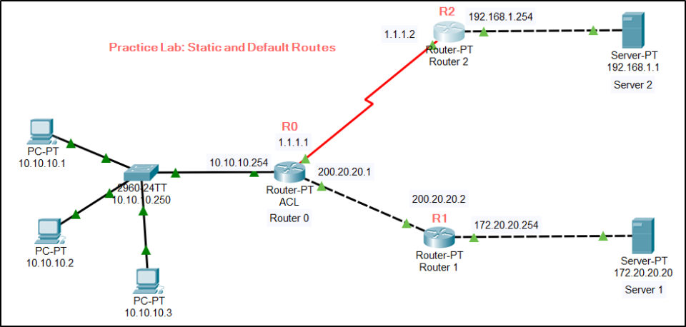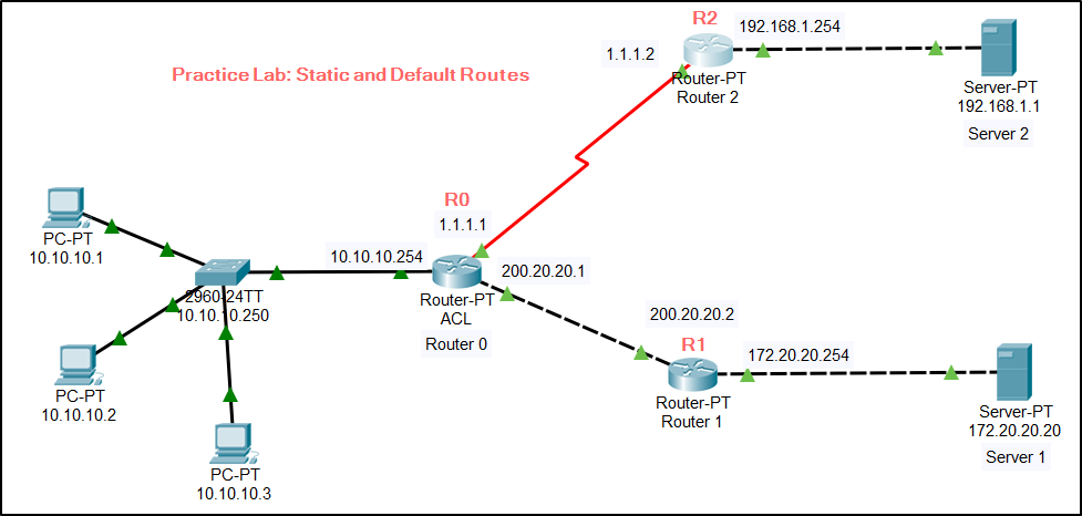
Network Topology Diagram:
Cable Connectivity:
- Cross cable connectivity between R0 and R1 & R1 and Web Server.
- Serial cable connectivity between R0 and R2.
- Straight cable elsewhere.
Basic Configuration:
On SW1
# interface FastEthernet0/1
# switchport access vlan 10
# interface FastEthernet0/2
# switchport access vlan 10
# interface FastEthernet0/3
# switchport access vlan 10
# interface Vlan10
# ip address 10.10.10.250 255.255.255.0
In PCs – Configure IP address as 10.10.10.1/24 and 10.10.10.2/24 with default gateway of Router R0 IP address 10.10.10.254
On R0
# interface FastEthernet0/0
# ip address 10.10.10.254 255.255.255.0
# interface FastEthernet1/0
# ip address 200.20.20.1 255.255.255.0
# interface Serial2/0
# ip address 1.1.1.1 255.255.255.0
On R1
# interface FastEthernet0/0
# ip address 172.20.20.254 255.255.255.0
# interface FastEthernet1/0
# ip address 200.20.20.2 255.255.255.0
On R2
interface FastEthernet1/0
ip address 192.168.1.254 255.255.255.0
interface Serial2/0
ip address 1.1.1.2 255.255.255.0
In S1 Server – Configure IP address as 172.20.20.20/24 with default gateway of Router R1 IP address 172.20.20.254
In S2 Server – Configure IP address as 192.168.1.1/24 with default gateway of Router R2 IP address 192.168.1.254
Scenarios:
Following are the scenarios for you to carryout in the lab to practice default and static routes.
Scenario I – Configure default route on routers to ping between PCs and Server 1
R0
ip route 0.0.0.0 0.0.0.0 200.20.20.2
R1
ip route 0.0.0.0 0.0.0.0 200.20.20.1
Scenario II – Configure static route on routers to ping between PCs and Server 2
R0
ip route 192.168.1.0 255.255.255.0 1.1.1.2
R2
ip route 10.10.10.0 255.255.255.0 1.1.1.1
Scenario III – Configure static route on routers to ping between Server 1 and Server 2
I leave this scenario to you to configure required routes and answer your results at the comment.
[ddownload id=”2769″ text=”Packet Tracer – Static and Default Route”][ddownload_filesize id=”2769″]


